


US-based Duggan Manufacturing was formed by friends Rodney Westich and Tony Pinho in Almont, Michigan 22 years ago. The company owes its success to hard work, smart investments and great customer service, with Prima Power at its side. Today the company has 90 employees working in a main facility of 72,000 sq ft and a satellite building of 28,000 sq ft.
“We devised a plan to get business rolling, and from that point on, it’s been a steady reinvestment plan for the latest machine technology,” explains Westich. “We put as much money back in the company as possible.”
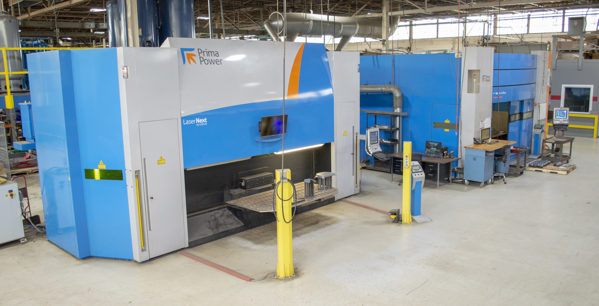
A large part of that investment plan has been dedicated to Prima Power 3D fibre lasers.
“When we began our search for lasers, Prima Power was one of several options,” says Westich. “The company was very helpful and open. They arranged for us to visit other customers who were doing laser-tube cutting and knew we were looking at something special. Their lasers are versatile and robust, with high uptime – but if there is a problem, Prima Power’s service department responds quickly and with excellent telephone support.”
Duggan purchased a 2 kW Prima Power Rapido fibre laser in 2010 and another in 2011. The company purchased a Prima Power 4 kW Laser Next in 2016.
“We’re not a huge company, but our three Prima Power lasers allow us to punch above our weight, meaning we have much more influence than we anticipated because they give us the same attention that you would expect for a large customer with multiple machines,” states Westich. “This type of key investment definitely helped us to grow.”
For further information www.primapower.com