Precision subcontract specialist, G-Mach Engineering, a company committed to continuous improvement and providing customers with best-in-class, high-quality machining services, continues its long-standing relationship with Mills CNC by investing in another high-performance machine.
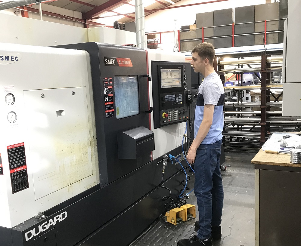
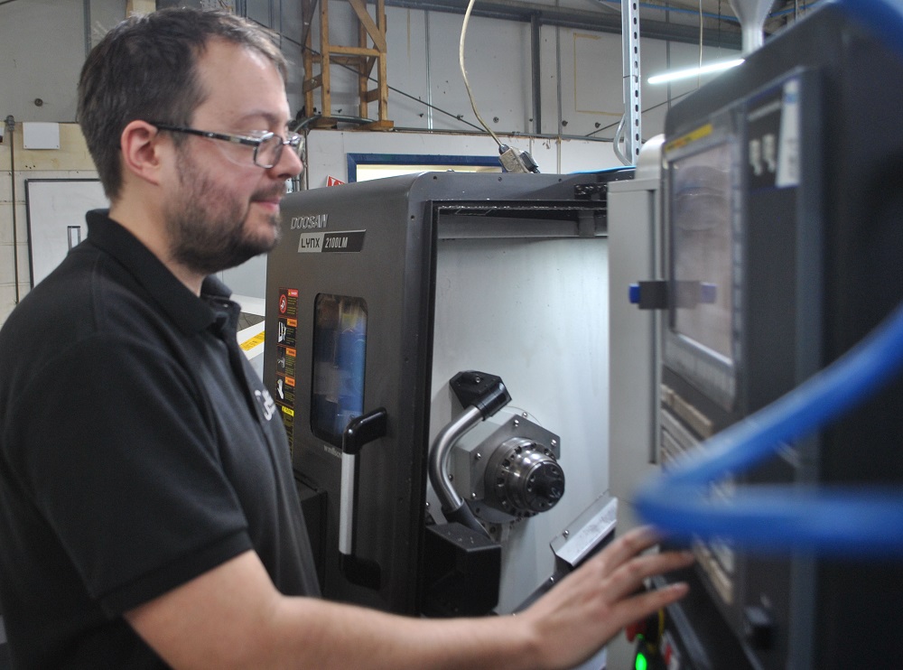
Mills CNC, which is the exclusive distributor of DN Solutions (formerly Doosan) and Zayer machine tools in the UK and Ireland, has recently supplied G-Mach Engineering, which celebrates its 30-year anniversary in June this year, with a new Doosan, FANUC-controlled, multi-tasking turning centre. The compact, 8” chuck/65mm bar capacity long-bed Lynx 2100LMB lathe with integrated driven tooling, arrived at the company’s 10,000sq ft production facility in Melton Mowbray in late 2022.
As a point of note, the new Lynx lathe is the latest addition to G-Mach’s impressive in-house machining resource which currently comprises 22 CNC machines in total (eight machining centres and 14 lathes), 17 of which are Doosan machines supplied by Mills CNC.
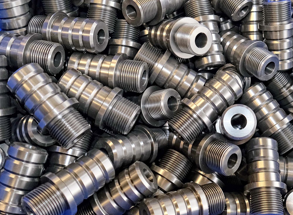
Since being installed, the new Lynx lathe has been put through its paces machining high-precision, complex components for the company’s growing range of customers operating in the motorsport, medical and aerospace sectors, to name but a few.These components, often with short cycle times (typically around 3 minutes), are made from a range of materials that include 316 stainless steel, titanium 4 and 5, Hastelloy, Inconel, aluminium and steel. The machining of parts takes place in relatively small batches (up to 2000-off), to tightgeometric tolerances of around 0.01 mmand stringent surface finishes down to Ra 0.8µm.
The 6000rpm driven tooling capability on the Lynx 2100LMB enables G-Mach to turn, mill, drill and tap small parts to completion in one set-up, improving the company’s productivity and process efficiencies, and enabling it to improve throughput and reduce production bottlenecks and pinch points.
G-Mach is a keen advocate and proponent of multi-tasking machine tools and, way back in 2000 when the company first started its relationship with Mills CNC, invested in its first multi-tasking machine: a Puma 230MSB sub-spindle lathe with driven tooling.
Says Graham Miller, G-Mach’s owner and director: “We’re an innovative and progressive company and, to differentiate ourselves in the market and maintain our competitive edge, we’ve always invested in advanced machine tools.A majority of these have been Doosan machines supplied by Mills CNC.”
He continues: “In the past four years alone, we’ve invested in five new Doosan machines.
Doosan machines are accurate, reliable and deliver excellent cutting performance. They are backed by Mills CNC’s aftersales service and support which, we believe, is the best in the business.”
A cursory view of G-Mach’s history reveals that the company invests in at least one new machine tool every year. This commitment to continuous improvement and growth extends far beyond new machine tool acquisitions.The company is constantly expanding, re-developing and improving its facility and, in 2022 prior to the arrival of the new Lynx 2100LMB and with the help of Mills CNC, G-Mach re-organised its machining operations to create separate and discrete turning and milling ‘sections’ within its facility.The re-organisation necessitated the quick, seamless and simultaneous movement of 17 machines.
“The re-organisation, achieved with help from Mills CNC, has helped us improve workflow and achieve significant machining efficiencies,” states Miller.
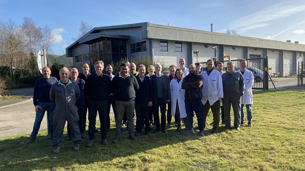
Other improvements implemented by the company to help cope with growing demand for its services, include the recruitment of four additional members of staff over the past three years.The company’s current head count stands at 20.
Even during the pandemic, when many companies were postponing or scaling back their investment plans, G-Mach was on the front foot and, in March 2020, successfully acquired a small plastic-part subcontract machining specialist as a going concern.
Says Miller:“The acquisition has helped us to diversify our operations further and, during the height of the pandemic, provided an additional revenue stream that offset a temporary decline in business from existing customers.Today, our plastics business accounts for 10% of our total turnover and, since 2020, as a direct result of our acquisition and investment strategies, turnover is up by 50%.”
Such impressive results, achieved through organic growth and by successfully entering new markets and sectors, is testament to G-Mach’s vision and values, and can be traced right back to 1993 when the company was first established.Then, operating as a one-man band from small, rented premises, and armed with a used NC lathe, a couple of manual machines and assorted tooling, G-Mach, led by Miller, began trading.
“Even in the early days, the focus was on delivering high-quality, added value and competitively-priced machining services, and on providing transparency and unrivalled customer service,” he says. “These same values and principles, which have stood us in good stead, remain cornerstones of the business today and will be for the foreseeable future.”
As far as the future is concerned, G-Mach, as one might expect, is not resting on its laurels.
To improve its machining capacity and capabilities the company will continue to upgrade its existing machine tool resources, trading in older models for advanced multi-tasking machines where appropriate.
G-Mach is also currently exploring the use and application of collaborative robot (cobot) technology to improve its productivity and part processing efficiencies.These potential investments, plus further redevelopment of its Melton Mowbray facility, will provide the company with a solid platform to achieve significant growth in the future.
With such an illustrious past and impressive track record, no one would bet against it happening sooner rather than later.
For further information www.millscnc.co.uk