


A company specialising in renewable energy is seeing major changes in the components it is being asked to produce for electric vehicles.

HV Wooding Ltd works at the high end of the electric vehicle (EV) market, manufacturing parts for two technologies in the powertrain, involving the battery and the motors. Customers include companies across the spectrum of electric vehicles: tier-one and tier-two suppliers of big name car marques; supercar manufacturers; supercar e-racing; electric motorbike GP racing throughout Europe; railways; aerospace; and (increasingly) electric buses, construction and agricultural vehicles.
For the battery, the Kent-based company makes a wide range of customer-specified busbars, forming part of the electrical connection, along with modular busbars that connect the battery to the rest of the vehicle’s configuration.
The other key area for HV Wooding is around the electric motor itself, producing specialist products both for the drivetrain and in-wheel. While most of the company’s parts, both for busbars and motor laminations, are cut from sheet material on a Trumpf CNC laser cutter programmed with Radan CADCAM software, HV Wooding also uses wire erosion, mainly for prototyping and developing small series production.

Sales director Paul Allen says Radan is also used as part of the process of quoting for jobs: “For example, most busbars are made from copper or aluminium, so we’d input the relevant material, such as 4 mm copper, and lay the proposed parts out in a Radan nest. This calculates accurate material usage and prices, in order for us to present the most commercial and cost-effective solution to the customer. Then, when we’re ready to go into production, we’ve got a finished nest already in a file.”
Allen says that as every busbar is different, Radan is proving vital for nesting a wide variety of shapes and sizes of the same thickness.
“If we were to do all this manually, the quotation process would take much longer and may not be accurate,” he states. “And we’d need to carry out a lot of manual work before manufacturing to get the best material usage. So Radan is essential in that it speeds up both our quotation and manufacturing processes.”
Notably, the Radbend module is used to calculate bend angles, and the order of bends for forming the busbars into a variety of configurations.

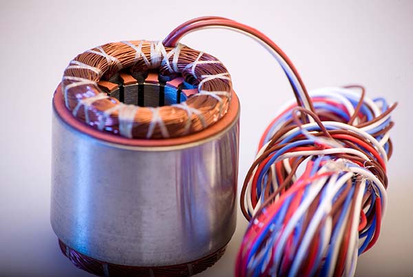
Radan also plays a major role in manufacturing motor laminations – several thin pieces or sheets of electrical steel or cobalt iron cut on the laser and bonded together to form the core pack.
“It’s vital that these parts are high precision,” states Allen. “The busbars and laminations are all required to be cut to tight dimensional tolerances, sometimes down to 50 µm for laminations.”
Higher end electric motors increasingly need thinner electrical steel, meaning the amount of adhesive applied becomes more significant, with as much metal as possible in the motor, and not so much adhesive.
HV Wooding has identified gaps in that market and is now actively seeking ways of making a breakthrough to provide a specialist solution. To this end, the company is working to develop a process for accurately applying a bonding agent to the electrical steel. Some types of material are available that come pre-coated with adhesive, but not the very thin grades in low volume and cobalt iron, which are becoming more prevalent.

“With this in mind, we’re working closely with a university and industry on a bonding process that will enable us to design motors, produce and test a prototype using Radan, and get them to market much quicker,” explains Allen.
Many of the company’s customers are working on projects involving battery technology, looking at battery life to improve the distance a vehicle can travel on a single charge.
“A lot of new designs using different grades of copper and aluminium are coming through to us, and they’re also looking closely at the insulation of the busbars,” says Allen. He goes on to says that the change is being driven by the need to gain more power from the motors, with electrical steels becoming increasingly more important for motor performance.
In conclusion, Allen says the market is extremely dynamic, which is why the company continually invests in line with current demands.
HV Wooding offers a wealth of engineering resources, skills and experience with a team of 100 people over multi-sited facilities totalling 53,000 sq ft. The company’s operation is approved to ISO 9001, ISO 14001 and OHSAS 18001.

“HV Wooding has been established for 50 years, diversifying from traditional switchgear, through renewables and data centres, and now to electric vehicles and drivetrain,” he says. “As a result, we now need different technologies and processes to take full advantage of the new opportunities relating to our core activity, particularly around assemblies. Radan is a key part of the processes we have in place to make a one-off component, right up to
high-volume production.”
For further information
www.radan.com