Automated and networked machines, digitalised process chains and autonomous transport
systems: the industry trends at the EMO 2025 exhibition this week (22-26 September)
almost give the impression that humans are no longer needed in production facilities.
However, experts from science and industry disagree with this idea. They explain that it is,
in fact, true that technology does allow production activities to operate with fewer
employees, which is vital in view of the current shortages of skilled workers.
And yet humans remain indispensable when it comes to maintaining an overview of
complex situations and being able to intervene as necessary. Assistance systems and, more
recently, AI are helping to make this as easy and safe as possible. And this is a development
that could increase the attractiveness of jobs in production.
The shortage of skilled workers is currently affecting the operations of many companies
worldwide. According to surveys by the Munich-based IFO Institute, almost one in three
companies in Germany alone complain that they cannot find enough skilled workers. The
reasons are complex and cannot be attributed solely to demographic change.
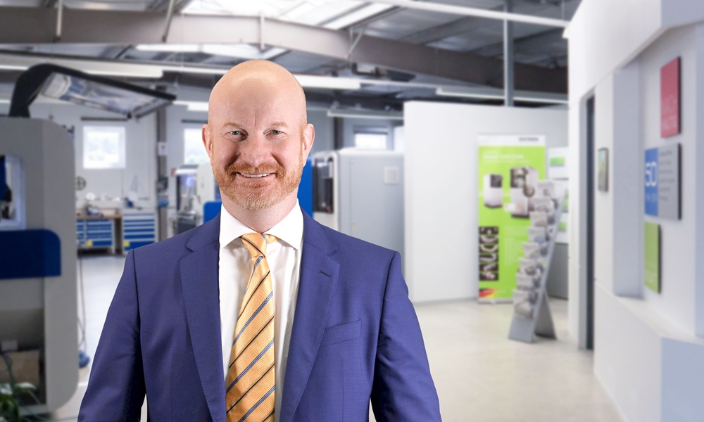
“It’s often not just a lack of personnel, but also a lack of efficiency,” says Michael Daniel,
CEO of machine tool manufacturer Datron AG. “As a machine manufacturer, we see it as our
responsibility to offer solutions in precisely this area.”
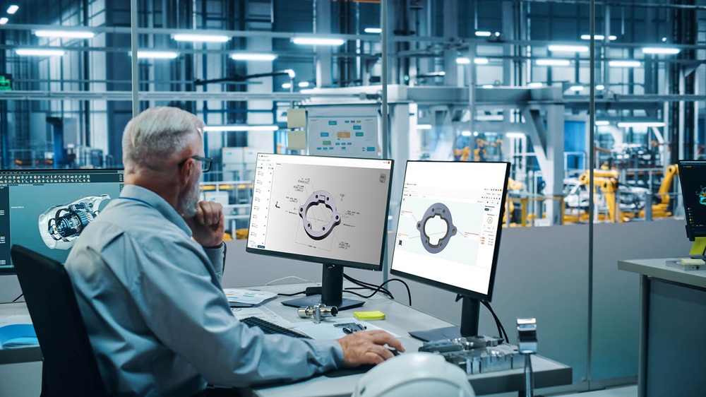
According to Daniel, modern machines, automation and digital assistance systems make it
possible to achieve more with fewer staff, while at the same time improving quality and
reducing the workload on employees. At Datron, this primarily means that machines are
becoming ever smarter, thanks to adaptive control systems, integrated sensor technology
and intuitive user interfaces. As a result, even less experienced operators can achieve highly
accurate results.
The company also sees a strong future for assistance functions that guide users step by step
through processes, help to prevent mistakes and reduce training costs. According to Daniel,
another focus of the company is on the digitalisation of workflows. From CAM programming
through to machine feedback, this approach produces a continuous flow of data that
creates transparency and identifies areas of potential for optimisation – for example in
terms of set-up times, energy consumption or maintenance cycles.
“We believe in technology that isn’t simply there for the sake of it, but instead is geared
towards the user in order to really make their jobs easier and improve efficiency,” he says.
Dr Elisa Roth, CEO of Munich-based Augmented Industries, also has a strong interest in the
technical possibilities for assisting production workers as effectively as possible. She
completed her doctorate at Cambridge University’s Institute for Manufacturing on the topic
of technology-supported learning and worker assistance systems. The range of solutions she
studied extended from exoskeletons and smart eyeglasses through to virtual and
augmented reality. Roth came to the conclusion that, although the technology has
fascinating potential, much of it has proven to be overly complex and sometimes technically
unstable or uneconomical.
“It doesn’t always fit in to a production setting,” she says. “There is a need for stability, quick
wins and minimal update requirements, while at the same time giving employees as much
freedom to operate as possible.”
As co-founder of Augmented Industries, a key area of focus for Roth is on the use of AI for
an individual worker assistance system that can be used directly in production and service
alongside the worker’s day-to-day activities. Depending on the operational requirements, it
can be used on many different types of device, whether it be a touchscreen, PC, smartphone
or tablet. The AI is supplied with information that is relevant to both the company and the
particular processes involved. It can create digital step-by-step instructions and answer
questions, which in turn helps to break down workers’ inhibitions.
“We found that many employees find it easier ask the AI questions, rather than admit that
they don’t know certain things to their supervisors or fellow workers,” explains Roth.
She also believes that the trend in training and further education is clearly moving towards
digital solutions, because companies can increasingly ill afford to have employees absent for
training purposes. There is also a lack of good trainers, so no other option is available than
to provide support digitally. However, off-the-shelf training material is of little use in
production settings where around 70% of the required knowledge is specific to the products
and processes involved.
The advantage of AI for training is that all of the information comes only from the company
itself and can then be prepared for training purposes. For example, the AI can turn a 100-
page work instruction document into numerous smaller ‘knowledge nuggets’, each taking
no more than 3-5 minutes to complete and therefore easy for the worker to retain. Content
can be prepared as step-by-step instructions, quizzes, multiple-choice questions or
interactive swipe tasks, which can be easily set up by the respective production or service
manager without external help.
An additional advantage for the purposes of qualification management is that the system
records who has already completed which training courses, assigns worker-specific content
and can provide information on who is qualified and can be assigned to a job or service task
accordingly. This automated qualification matrix saves forepersons and team leaders the
need to carry out additional data entry work as part of ISO9001 audits.
Augmented Industries spent more than two years developing its human-centric AI agents,
explains Roth, while taking all safety mechanisms and relevant compliance rules into
account. Customers now include companies such as Siemens, BMW and ZF, and ambitious
targets have been put in place:
“By 2030, we want to train around one million skilled workers,” states Roth.
Another of the company’s reasons for attending the EMO 2025 is to find out about trends in
production technology and thus gain further insights into possible training topics.
Training and educational topics have always been an integral part of the EMO, which
features a special education showcase, helping the trade fair to establish itself as one of the
most important platforms for promoting young talent in mechanical and plant engineering.
The special showcase is a joint initiative of the Nachwuchsstiftung Maschinenbau
foundation for training in mechanical engineering and leading technology companies from
the metalworking sector. Industry viewpoints and talks will focus on trending topics such as
future skills, artificial intelligence in training and new learning environments for vocational
training.
Great efforts are being made to get young people in particular interested in production
technology. Professor Jutta Rump, director of the IBE (Institute for Employment and
Employability) at the Ludwigshafen University of Business and Society, recently emphasised
that an equally great effort should be made in order to keep skilled workers in production
for as long as possible and enable them to adapt to a rapidly changing world of work.
In the Tech Affair podcast of the VDW (German Machine Tool Builders’ Association), she
calculated that around 13 million skilled workers in Germany will retire from the labour
market by 2030, but only 6.5 million new people will come up through the ranks to replace
them. She believes that not only do companies need to invest much more in their
productivity than before.
There is also an urgent need for professional HR management aimed at proactively training
employees. She explained that, especially in times of structural change, with job cuts in
some areas going hand in hand with shortages of skilled workers in others, reskilling is
important to open up new prospects for workers in areas where there is a need. It could
basically be seen as negligent if we fail to focus more on the needs of certain groups, such as
older workers, skilled foreign workers whose language skills may not be up to scratch or
women with children that they cannot find suitable childcare for.
When it comes to acquiring staff, the ability to offer suitable jobs and individual support are
key factors, explained Rump.
Datron CEO Michael Daniel shares a similar view, emphasising how important it is to
promote further training with individual development paths that are geared towards
people’s strengths and interests. Employees appreciate the freedom to be able to work
independently, whether in production, service or development.
Daniel is convinced of this fact: “What makes us attractive is a culture that recognises
performance, respects the work-life balance and allows for development.”
More information www.emo-hannover.de/en