Strategic and prudent investment in advanced Doosan machine tools is helping contract manufacturing specialist, Oxford Engineering Ltd (part of the Oxford Engineering Group), achieve significant organic growth, secure new business wins and deliver high-quality manufacturing solutions congruent with its aspirational and motivational vision statement.
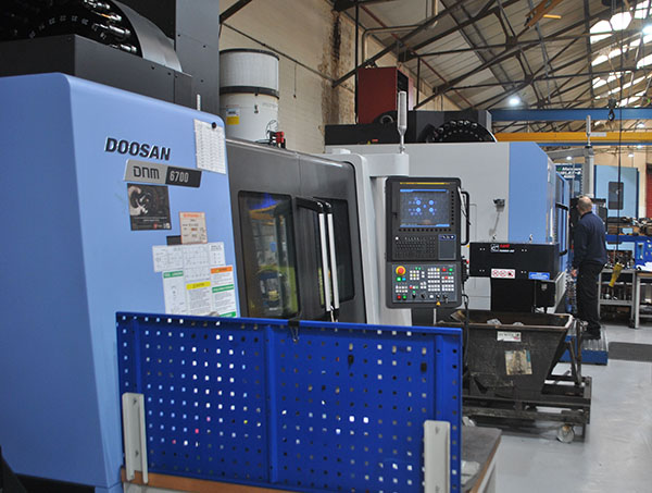
Mills CNC, the exclusive distributor of Doosan machine tools in the UK and Ireland, has recently supplied the company with three new multi-tasking machines. The machines, all DNC-linked and equipped with the latest FANUC controls, comprise a DNM 6700 vertical machining centre, a 10/12” chuck SMX 2600S turn-mill machine, and a 21” chuck (large-capacity) Puma 5100MB lathe.
The machines were delivered and installed at the company’s well-resourced machine shop facility over a six-month period (October 2021 – April 2022) and have taken their place alongside the company’s (but not the group’s) first Doosan machine tool investment – a DNM 750L II vertical machining centre acquired in June 2019.
Says Karim Sekkat, CEO, Oxford Engineering Group: “Doosan machine tools, supplied and supported by Mills CNC, are technically excellent machines. They are flexible and reliable, deliver outstanding accuracy and repeatability, and help us keep our quality, delivery and cost promises to our customers.”

He adds: “We now have four Doosan machines installed at Oxford Engineering Ltd’s facility in Abingdon but, across the whole group, the number is considerably higher, with our two Hutton Engineering facilities, in Bicester and Abingdon, having a total of over 20 Doosan machines between them.”
However, it is not just the technical capacity and capabilities of Doosan machine tools that have made, and continue to make, them so attractive to Oxford Engineering: it is the service and support provided by Mills CNC that adds to their appeal.
“Doosan machines are reliable but, if and when, any issues arise that affect their performance or cause downtime, we know that Mills’ after-sales and support services will help keep any disruption to our and our customers’ production schedules to a minimum,” says Sekkat.
Oxford Engineering Ltd, is a vertically integrated contract manufacturing specialist that provides a range of high integrity services and solutions, which include technical consultancy, precision machining, welding, fabrication, assembly and testing, to a growing number of global customers operating in the medical, nuclear, semiconductor, aerospace, defence and scientific instrumentation sectors.
Like all other companies in the group (such as Hutton Precision Engineering and Oxford Engineering Estonia), Oxford Engineering Ltd is characterised by its data-driven approach, where the company acts and makes decisions based on facts and manufacturing KPIs, as opposed to ones based on guesses, anecdotal evidence or ‘gut’ reactions.

As such, this strategy, focused on the collection, processing and interpretation of real-time data (gained from a variety of sources that include the company’s shop floor equipment and MRP/ERP systems), enables senior managers to continuously monitor and benchmark performance against KPIs, identify issues and factors that affect/impact upon productivity, spot emerging trends and opportunities, and make strategic and timely interventions to ensure process optimisation.
“We operate in highly-regulated markets where there is an emphasis on continuous improvement, innovation, traceability, process reliability and cost reduction,” states Sekkat. “To ensure we are able to provide our customers with the best possible service and solutions, we adopt a holistic approach that covers all aspects of production, including supply chain management and logistics issues, lean manufacturing methods and imperatives.
“In this way we are able to build and customise our manufacturing operations and processes around individual customer requirements,” he continues. “As such, our customers have come to expect, and now rely on us, to have advanced manufacturing technologies and optimised processes in place to help them outperform their competitors and delight their customers.”
To ensure that this can occur, Oxford Engineering has implemented a company-wide continuous improvement programme and, as such, makes regular investment in its people, plant and equipment, as well as its processes and systems. For example, in addition to the recent investment made in the three new Doosan machine tools, the company has significantly strengthened its metrology/inspection credentials with the acquisition of a laser-driven Global S Chrome coordinate measuring machine (CMM).
“It’s all about being the best we can possibly be,” says Sekkat.
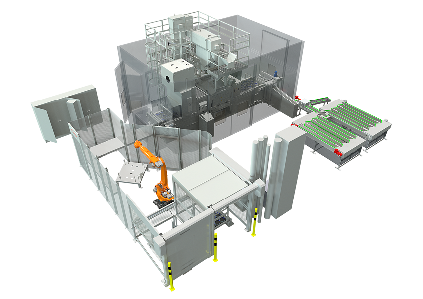
The three new Doosan machines acquired by Oxford Engineering comprise an advanced vertical machining centre with a 4th-axis unit, a multi-axis turn-mill machine featuring an integrated bar feeder and a large-capacity turning centre with large bore capabilities and driven tooling. Mills CNC says these machines provide Oxford Engineering with reliable cutting performance and flexibility and, irrespective of the materials machined or the part accuracies and/or surface finishes required, are more than up to the task.
The latest machine tool investments also highlight and encapsulate Oxford Engineering’s technology preferences and imperatives, namely to invest in FANUC-controlled Doosan multi-axis and multi-tasking machines with integrated automation.
Says Sekkat: “We know from our group experience that multi-tasking Doosan machines from Mills CNC supplied with integrated automation are proven performers and help us reduce job set up and part cycle times, avoid production bottlenecks, ensure improved asset utilisation and meet ever-stringent customer delivery deadlines.
“We work in partnership with customers to create strong, mutually-profitable and long-term strategic alliances,” he concludes. “Our investment in Doosan machines tools from Mills CNC is an important cornerstone in establishing and maintaining these relationships.”
For further information
www.millscnc.co.uk