


Arturn Precision Engineering has invested in a Hanwha XD38II sliding-head turning centre from Dugard to enhance capacity and throughput at its Rugby-based facility. As a tier-one automotive supplier, as well as a manufacturer for the fastener, electrical, food and pharmaceutical industries, Arturn is no stranger to high-volume production runs, which is where the Hanwha machine from Dugard is making a difference.
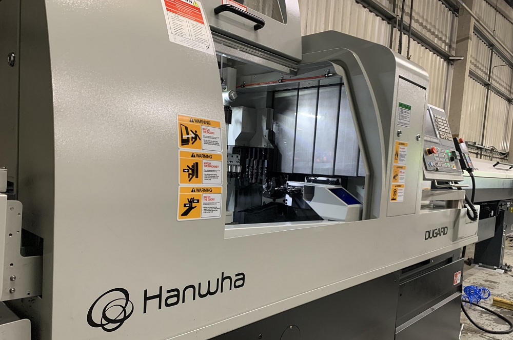
Myles Rudkin, foreman at Arturn Engineering, says: “One of the main reasons we bought the Hanwha XD38II is because we can turn up to 38 mm diameter on a sliding-head machine, which in my opinion is pretty impressive, especially when the sweet spot is from 32 to 38 mm. That’s where we have a broad diameter of parts, so it means we can expand the range of components which we can machine for customers.”
Looking at the specific attributes of the machine, Rudkin adds: “It’s a great machine and, where the tools are located, particularly the power tools, makes it easily accessible to interchange cutting tools and accelerate our set-up processes.”
Considering the FANUC 32i-Model B CNC system and the programming, Rudkin says: “I like the programming on this machine. It has broadened my knowledge because a lot of the M codes are familiar, like on a fixed-head machine. This means that my knowledge of fixed-head machines and the respective G- and M-codes will transfer directly to the Hanwha.”
With flood coolant on the new Hanwha XD38II sliding-head turning centre, ISO9001-accredited Arturn has noticed a marked improvement in tool life.
“The coolant flow on this machine is excellent and there is a high number of coolant hoses on the machine that can be moved and directed at specific tools,” says Rudkin.
For further information www.dugard.com