

CADCAM specialist Open Mind has identified rapid growth with its automated program generation. In fact, the company estimates that the number of automation projects among users of the hyperMill CADCAM suite tripled in 2020. At the same time, demand for hyperMill Automation Center Advanced has increased significantly.
“The more powerful that machining centres and tools become, the more often CAM programming becomes a bottleneck,” explains Rico Müller, project manager for CADCAM automation at Open Mind Technologies AG. “Companies are looking for solutions that allow them to make their CAM programming more efficient by automating processes. Even the most complex and diverse workpieces are created based on a large number of similar operations that can be standardised. In hyperMill, tool databases, feature recognition and macros for standardisation have been available for some time. However, they are now being more commonly adopted across the manufacturing industry to automate CAM program creation.”
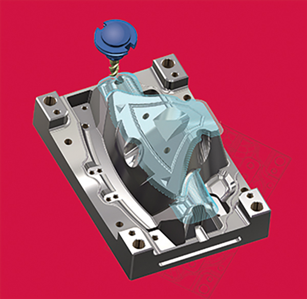
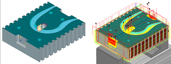
Even the basic version of hyperMill Automation Center allows users to automate the job list creation process, and select and position clamping devices. In addition, a uniform process can be defined for all programmers. The Advanced version makes it possible to define and standardise even complex processes, where the solution primarily focuses on the individual elements of a CAD model. Here, the steps for data preparation and programming, right up to simulation and NC program generation, can all be defined.
Once a manufacturing process has been defined, it can be applied to any new component and executed automatically. If any decisions cannot be made with complete certainty within the automated process, the user is prompted to make the relevant choices during the program run.
For further information
www.openmind-tech.com