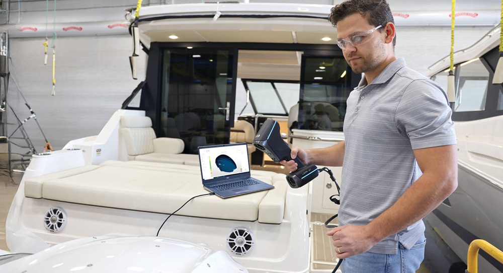
A BRIEF HISTORY OF CAM SOFTWARE SIMULATION BY DR YAVUZMURTEZAOGLU, FOUNDER AND MD OF MODULEWORKS

In the world of computer-aided manufacturing (CAM), simulation technology has evolved
from a luxury to what many consider an essential component. As we explore the landscape
of CAM software today, three questions consistently emerge: Is the simulation of tool paths
in CAM truly a must-have or merely a nice-to-have feature? What capabilities should we
expect from simulation in today’s modern CAM software and powerful hardware? And
perhaps most importantly, what developments can we anticipate in the coming years?
I would like to take you on a journey through my last 30 years in this field, sharing insights
and findings from my experience. This personal perspective will trace the evolution of
simulation technology from its early rudimentary forms to today’s sophisticated solutions,
providing a comprehensive understanding of where simulation technology stands in modern
CAM.
In 1997, 3D CAM was still very new. Five-axis machining was an even smaller niche, and
professionals used the term “true five-axis machining” to describe the continuous motion of
all five axes simultaneously. The majority of customers were performing what we called
“indexed” or “3+2 axis machining”, where the machining direction remained fixed for each
tool-path operation.
I was fortunate to be in Germany, where machine tool vendors were increasingly
introducing five-axis CNC machines to the market, and control makers like Siemens and
Heidenhain were enhancing their capabilities to support these advanced machines.
During this period, I was developing five-axis tool-path algorithms to overcome CAM
software limitations, enabling customers to machine complex shapes across various
industries. However, determining whether a tool path was safe presented significant
challenges. The integrated simulation in CAM software utilised back-plot technology to
display the tool tip as a series of lines – effective for 2D or three-axis machining but
inadequate for five-axis machining, where the tool tip could maintain its position on the line
while the tool itself tilted.
The material removal simulation integrated into these systems effectively demonstrated
how parts were created from stock material but failed to identify potential collisions when
all machine components were in motion. Dedicated stand-alone simulation software was

available, but it required separate licensing, installation and considerable patience to
evaluate each program.
We soon recognised that the most significant risk in five-axis machining was machine
crashes. To address this, we began simulating complete machine kinematics. Given the
complexity of machine geometry, we focused on simplifying it, concentrating on critical
components such as the table, work holding and spindle, while disregarding the housing and
other less critical details.
We discovered that OpenGL, well-developed for gaming, could be leveraged to create fluid
animations of machine movements for any five-axis tool path. The challenge was converting
CAM software tool paths to machine motion. The solution lay in the post processor: its role
is to transform the tool path for the part to machine kinematics, mathematically converting
the tool-axis vector in the workpiece co-ordinate system into rotary axis angle values for the
specific machine.
Since five-axis post processors were rare, we developed this capability in-house. Our post
processor developers provided the kinematic solution, which we connected to an OpenGL
engine. The result was a fast capability for simulating tool paths for any five-axis CNC
machine. By the early 2000s, we showcased this technology at a major exhibition on a large
screen.
While fast, this system initially did not report collisions. Nevertheless, it proved valuable.
We termed it “Visual collision checking”, similar to tool-path back-plotting where users
manually inspect the tool path. Operators could run the simulation, rotate the view with the
mouse and visually determine if collisions would occur. Given the comparative slowness of
computers at that time, this represented a pragmatic solution, offering instant simulation
without waiting time. Users could navigate between the program’s start and end points
simply by moving a slider bar with the mouse, visualising all motions.
We decided that our five-axis tool path should be used in conjunction with this simulation
and bundled them together to prevent machine damage due to inadequate simulation
capabilities. While some customers purchased additional stand-alone simulation packages,
most found our fully integrated simulation extremely helpful since it utilised the same
kinematic solver as the post processor they employed to operate the machine.
As computer hardware became increasingly powerful, our ambitions grew: why not
implement actual collision checking instead of merely visual collision checking? Encouraged
by OpenGL’s success in gaming and how it facilitated our solution development, we
explored further gaming technology and collaborated with an expert who had developed
collision detection engines for the gaming industry. After significant investment and
adaptation to meet industrial needs, we achieved full collision checking, also known as
“clash detection”.

Accustomed to instant simulation capability, we aimed to maintain similar speed levels even
with collision checking. This presented challenges, but we discovered that by reducing the
number of triangles in the triangle mesh model, we could achieve satisfactory speeds.
At this stage, however, we were only addressing machine collisions and gouges of the tool
and spindle against the target workpiece geometry. While we could guarantee that the
target part would not be damaged by the tool and no machine collisions would occur, we
lacked material removal simulation, meaning unexpected cuts into unmachined stock went
undetected, such as a rapid motion crossing the stock. This required material removal
simulation, so we directed users to run the integrated material removal simulation engine
within their CAM software, typically licensed from specialist companies providing such
technology.
In 2005, at an academic conference, I met Dr Stautner from Dortmund University, who had
completed his PhD on material removal simulation technology and subsequently joined our
team. We were receiving numerous customer requests for fully integrated material removal
simulation within the machine simulator.
Upon examining existing market technology, we found that most CAM software utilised a
technology based on mesh Booleans, where tool motion is described as a mesh subtracted
from the stock mesh. While initially quick, the process slowed dramatically as more
Booleans generated increasingly more triangles. We adopted the discrete model originating
from Dortmund University but recognised the substantial work required to ensure accuracy.
Though fast, making the results visually appealing and supporting technologies like turning
and wire cutting presented significant challenges.
By 2015, our journey continued despite our satisfaction with our simulation technology. A
new challenge emerged: how to run the simulation engine on an industrial PC adjacent to
CNC control to prevent machine collisions in real time. This challenge came with the
advantage of receiving information about future machine movements with a one-second
look-ahead, providing data of the “future” one second in advance. Our task was to calculate
collisions and material removal and stop the machine before any issues occurred. This
necessitated significant optimisation of our calculation engine and required heroic efforts
from our team to deliver timely solutions to partners.
We named this technology CAS (Collision Avoidance System) and believe it could eliminate
all machine tool crashes. With the rapid advancement of chip technology, accelerated by
developments in AI, we anticipate that within a few years, even basic chips in CNC controls
will have sufficient performance, eliminating the need for additional industrial PCs.
While CNC machines can avoid collisions using CAS, it requires proper definition of the tool,
holder, work holding and stock geometry for each job. Many CNC machines do not require
such data to cut parts, but it is essential for collision avoidance. Upon investigation, we

determined that all this data exists within CAM software but lacked a standard format for
export to CNC machines – typically, only the NC program was transmitted.
We initiated the development of MDES (Manufacturing Data Exchange Specification) to
enable the export of job set-up data from CAM software to CNC machines running CAS.
Working with approximately 90% of major global CAM vendors and most CNC control
makers and machine tool vendors, we secured substantial support from key industry
players. The adoption of this workflow is progressing. To accelerate adoption, we have
made this specification freely available as an open standard to prevent the proliferation of
competing proprietary standards.
And the story does not end there. NVIDIA’s success with AI means we now benefit from GPU
power. The benchmark results on a mid-range GPU are fascinating: many tool paths with 1-3
million lines of NC code complete simulation at the highest resolution in under 10 seconds. I
confidently assert that material removal simulation should never take more than 10
seconds, regardless of tool-path size. We have achieved this without compromising quality
or taking shortcuts to increase speed. This approach facilitates straightforward retrofitting
for all CAM software companies using our solution, they do not need to change anything for
their users to enjoy this improved performance.
While one team focused on GPU simulation, another team worked with numerous
developers for years on triangulating our discrete model. We discovered that our discrete
model offered many advantages, including linear speed increases with more moves,
numerical stability and memory usage control. However, the triangulation was based on
discretisation.
We found a method to generate perfect triangulation based on customer tolerance
requirements without generating excessive or insufficient triangles while preserving
features like holes, sharp edges and fillets. This significantly improved simulation speed in
“play mode” and substantially accelerated the simulation engine used for updating stock
models between consecutive tool path operations such as roughing and rest-roughing.
As our CAM partners integrate and release these capabilities, users will soon access this
exciting technological suite.
More information www.moduleworks.com

Press provides 60% more production at Weldmac

Established in 1968, Weldmac Manufacturing is a job shop that offers laser cutting and welding for stainless steel, aluminium, titanium, Inconel, Hastelloy and other alloys, as well as machining, press-brake forming, hydroforming and spinning. The company’s latest machinery purchase, a custom 800 T triple-action hydraulic press from Beckwood, supplements its existing 150 and 450 T triple-action presses.

“At double the tonnage of our other triple-action presses and with a larger bed size, we’ve already increased capabilities by 50%,” says Weldmac president Marshall Rugg. “Ease of use due to programmability should push capabilities to a 60-70% increase. Operator capability enters into it, but the controls on this press only will make jobs easier for a good manual press operator.”

The triple-action press consists of a punch or forming tool on the main draw ram, a clamp ram in the middle, and a knockout cylinder and/or bed cushion on the bottom. The clamp ram, which offers individual tonnage control on each cylinder, is engaged throughout the forming process to control material flow and reduce wrinkling and tearing within the part. By giving operators the ability control material flow, they achieve greater success in forming parts.

Proportional control valves regulate the bed cushion, enabling dynamic control through four different travel zones. Through the HMI and recipe settings of the press, the operator can specify a desired bed cushion force at any position within each zone.

“We excel at building complex components and assemblies, and that work continues to increase,” says Rugg. “We’ve added customers that usually come to us with one problematic part or assembly, and that leads to more business. When we do a good job, a new customer gives us more things to do. New press capacity and capability helps us handle that.”

More information www.beckwoodpress.com

Most advanced press shop in MENA installed

Ceer, Saudi Arabia’s first electric vehicle (EV) brand and OEM, has partnered with Schuler to supply and install the first completely automatic press shop at its state-of-the-art Ceer Manufacturing Complex (CMC) in King Abdullah Economy City – said to be the most advanced manufacturing facility in the MENA region.

The CMC encompasses every stage of vehicle production, from press shop and body shop to paint shop and general assembly. It also integrates comprehensive logistics, waste management, warehousing, offices, a water treatment system and a dedicated vehicle test track.

Ceer’s latest milestone at the facility, just four months after raising of the first steel frame, is the start of the installation of the Schuler press shop, an important step in building the country’s EV sector. The partnership with Schuler is central to the manufacturing process, which is rapidly taking shape.

The press shop – including two press lines, a try-out press and a laser blanking line – is the nucleus of vehicle production where precisely cut metal blanks are transformed into chassis parts, and where body components like side frames, doors and bonnets are formed from sheet metal. Schuler’s presses and laser blanking lines offer an output of up to 64 parts per minute. Overall, the press and laser blanking lines offer high availability, flexibility and output, as well as decreased power consumption. Ceer’s press lines, powered by cloud-based applications, prioritise energy efficiency and sustainability.

This landmark partnership with Schuler marks a crucial first step in Ceer’s manufacturing process and will form the backbone of its EV production, paving the way for a new era of smart manufacturing in the region.

More information www.schulergroup.com

HMS Products joins the AIDA-America family

AIDA-America, a specialist in mechanical and servo press systems technology, has welcomed HMS Products, a manufacturer of press automation, to the AIDA family. AIDA and HMS have a long history of working together on turnkey solutions for customers. AIDA’s acquisition of HMS will act to strengthen further this partnership and benefit mutual customers with the resulting integrated stamping press system solutions tailored to the requirements of customers in North America.

President Kland Aida states: “Both companies are excited about the added value, as well as the additional expertise and collaboration opportunities that this new alliance brings to our customers.”

HMS will continue to operate from the company’s Troy, Michigan headquarters, with its 60-strong team remaining in place. Kevin VanDenBrouck has been appointed as COO of HMS and will lead the company into this new chapter. Under his leadership, HMS will continue to build on its 47-year history of in providing technologically advanced press automation equipment. This includes ‘through the window’ and ‘front and rear’ mounted transfer systems, blank de-stackers, custom front- and end-of-line solutions, and transfer tooling.

AIDA is a supplier of metal stamping presses and metal-forming equipment. Through engineering, manufacturing, sales, service and support, the company provides partnerships to numerous industries worldwide. AIDA servo and mechanical stamping presses are available in capacities from 35 to 4000 T and 1 to 800 strokes per minute.

Single-press, tandem-line, high-speed, lamination and cold-forging models for single-stroke, transfer and progressive-die applications provide a full range of production capabilities. Additionally, AIDA offers material handling and automation systems for turnkey solutions produced by a single manufacturer.

Sales, service, engineering and manufacturing locations in more than 40 cities across 20 countries support press installations exceeding 80,000 units in over 60 countries.

More information www.aida-global.com

Record-low TRIFR for Seco

Cutting tool manufacturer Seco hit a significant milestone in its H&S performance for 2024. The company recorded a total recordable incident rate (TRIFR) of 1.3, surpassing the target of 1.5 and achieving the lowest TRIFR in its history. It marks a substantial improvement from the 2019 baseline of 4.7 and reaffirms the long-term commitment of Seco to achieving zero harm. By 2030, the company aims to reduce TRIFR by 80% to 0.9 or less. Claudius Mpofu, sustainability & EHS coordinator, says: “Via continuous improvement, proactive initiatives and a strong safety culture, we’re making tangible progress toward our safety goals.”

More information www.secotools.com