


Several principals of Sheffield, UK-based machine tool dealer Ward Hi-Tech exhibited at Europe’s largest machine tool exhibition, EMO, in Hanover last week.
For instance, Korean-based machine tool builder, Hwacheon exhibited the new i2-2SP turn-mill machine. A high-specification model capable of machining complex parts in one set-up, the i2-2SP was equipped with the latest Hwacheon-developed Harmony user-friend control with the FANUC system at its heart.
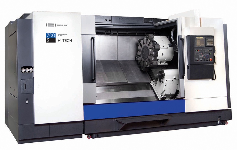
Also on show was the best-selling Hi-Tech 750ALYMC heavy-duty turning centre with driven tools and Y axis. Specifically designed for large workpieces and materials that are difficult to machine, the Hi-Tech 750ALYMC comes with up to 24” chuck size as standard and the Hwacheon extra-wide 12-station turret, benefitting the application of extra-long boring bars.
Elsewhere on the Hwacheon stand was the AF-4 horizontal, high-speed multi-pallet machining centre. As standard all models have a rapid traverse of 60 m/min in X, Y and Z, and up to 34 rpm on the B axis coupled with a high-speed tool changer and a 37 kW spindle motor.
Finally, the MEGA 72 is high powered flat-bed CNC lathe with a maximum swing of 720 mm and a turning diameter of 480 mm over the saddle through a heavy-duty spindle. Options include various turret types, steady sizes and heavy-duty tailstock and large-capacity side-mounted boring holder of up to 150 mm diameter.
Another Ward Hi-Tech principal at EMO was SFM of Taiwan, which has been building heavy-duty flat-bed lathes for over 60 years. At the exhibition, the company exhibited a CST46200 long-bed CNC lathe with a swing of 1170 mm, bed length of 5 m between centres, twin-chuck headstock with 255 mm diameter spindle bore, and 50 hp heavy-duty main motor.
More information www.wardhitech.co.uk