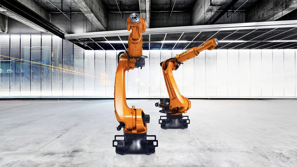
Manufacturing gear wheels in 34 seconds

Minimising production times to ensure competitiveness is one of the most important challenges in the automotive industry, a factor recognised by Henry Ford over a century ago. After decades of optimisation, it is difficult to reduce machining times further while maintaining the same level of quality. Nevertheless, Volkswagen (VW), near the German town of Kassel, has managed to achieve this in its gearbox production facility using Kapp Niles gear grinding machines available in the UK from the Engineering Technology Group (ETG).

The Volkswagen plant in Baunatal is one of the group’s larger German locations with a workforce of about 17,000. Production here focuses mainly on car gearboxes in 10 different series. Half of the manufacturing lines feature gear production centres from Kapp Niles.

Kapp Niles machines also find use in the production of the DL382 dual-clutch gearbox for Audi. A total of 16 gearings are required to shift the seven gears within this type of gearbox – 10 ground and six honed. The production unit runs 24 hours a day, 5 to 6 days per week, depending on demand. VW strives to achieve an EPEI (every part every interval) value of 1 day in the production unit, which means that all components can be produced on each day for the aforementioned gearbox. This type of streamlined production requires seamless processes and a high degree of flexibility.

Technical clerk Christian Hahn is in charge of the production process of the DL382 dual-clutch gearbox: “We have five gearing centres from Kapp Niles in the wheel production unit and two more in the shaft production unit. To achieve an EPEI value of 1 day, we change over the machine in the wheel production unit twice every 24 hours. This way, we can produce 10 different wheels per day.”

The challenge with flexible production is the short cycle times. With an output of 880 gearboxes per day, one machine in wheel production must produce 1760 parts per day. Including all set-up times and failures, this yields a line cycle time of 34 seconds. An average line cycle time is 39 to 40 seconds.

Bernd Kümpel, application technician at Kapp Niles, analyses these figures: “Saving 5 to 6 seconds per cycle does not sound like a lot at first, but together it can be a 15% reduction. If I consider that at least 40% of segments cannot be influenced, I have to reduce the actual process time by 30 to 40%. Seen in this way, 34 seconds is a real challenge.”

A total of seven Kapp Niles machines are deployed which, with their low space requirement, are suited to the highly automated production lines at Volkswagen. The machines include three KX 100 Dynamic, two KX 260 Twin in wheel production and two KX 160 Twin in shaft production.

Hahn and Kümpel agreed from the very beginning that the desired cycle time could only be achieved with a combination of several measures. To minimise the daily set-up effort, Hahn makes sure that the wheels which are to be produced on one machine have bore holes of the same size. Thus, he has to change over the machine, but not the clamping tools. The remaining set-up time is minimised by the intelligent set-up concept of the KX 100 Dynamic. For one machine, he needs just 20 to 25 minutes.

“The semi-automatic set-up makes the KX 100 Dynamic extremely user-friendly,” says Kümpel, describing the process. “All you need is an Allen key for the entire set-up operation. With it, you operate the hydro-expansion clamping chuck of the dresser roll. Everything else is connected without any screws via HSK interfaces.”

An additional visual aid is available in the form of a menu guide and an easy-to-understand cycle on the machine controller. By completing the step-by-step process and the acknowledgement screen, the operator ensures that no work steps are executed incorrectly or forgotten. It thus becomes possible to prevent high-cost failures. The tools are dressed using full profile rolls, allowing all threads of the cylindrical worm to be approached and moulded simultaneously. Thus, with a five-pass full profile roll, the dressing time can be reduced by more than half without compromising on quality.

The integrated measurement system is another important time-saver. Hahn explains the advantage: “After each changeover, quality measurement has to be made outside the machine. We continue to require this, but I can already check the basic, quality-related parameters with the integrated measurement sensor in the machine itself. It saves a lot of time since we can start production before the results of the external measurement are available.”

The integrated measurement system of the Kapp Niles machines thus accelerates the restart process considerably. Furthermore, the external measurement merely checks more teeth and generates the measurement report to monitor the gear.

The search for optimisation potential also includes the actual grinding process. Cubitron II machine tools by 3M show a highly promising approach with geometrically-specific, triangular-shaped cutter heads, compared with conventionally dressable grinding wheels.

“With these, you can step it up a notch, to say it plainly,” states Hahn. “That is, remove more material in one thread, and remove it faster.”

For this purpose, Kapp Niles provided relevant preparatory work with a large number of grinding tests in-house to use the benefits of this machine tool on the DL382 components.

Says Kümpel: “With CII you can remove a considerable amount of material without any thermal damage to the component. This way, we reduce time consumption by a solid 30% compared with other grinders, depending on the component.”

Production is characterised by a belt chaining (or linkage) that goes through the entire production hall. Among the employees, it has gained the nickname ‘the highway’. The available space is limited, hence the compact KX 100 Dynamic machines are the preferred choice. This machine type has two separate rotatable mounted columns, each with vertically movable pick-up axes featuring one workpiece spindle. While a workpiece is being machined, the other pick-up axis places the machined workpiece and loads a non-machined part on to the workpiece spindle. The workpiece is aligned outside the work area. This allows the workpiece spindle, already accelerated to machining speed, to be swivelled in the work area, keeping non-production times to a minimum.

A transfer unit does the loading and unloading from the conveyor belt. Kümpel says: “We usually move with the belt directly below the machine. However, this was not possible here. With the transfer unit, we compensate for height and distance from the belt to the machine. An integrated automation solution would have been significantly more expensive, at about 25% of the price of the machine. A simple transfer unit costs less than 10% of the machine price.”

The time for conversions and commissioning is, in most cases, very limited. But the highly ambitious goals have been achieved.
“Throughout the process, I‘ve been very satisfied with the on-site support and the local service,” says Hahn. “We were convinced by the machine concept and managed to overcome any obstacles together. The cycle time was a critical aspect. But, we did it.”

For further information
www.engtechgroup.com

DRAG FINISHING POLISHES TARGETED SURFACE AREAS ON HIP STEMS

To ensure the optimal function of artificial hips in a patient’s body, certain surface areas on the hip stem must have different finishes. For example, the neck area of the stems requires a very smooth, polished surface. Recently, a manufacturer of precision components replaced a combined manual grinding/electropolishing operation with a fully automated two-stage mass finishing process. The Rösler R 4/700 SF drag finisher allows the simultaneous, precise finishing of 12 hip stems in one operation. This performance resulted not only in significant cost savings and lower cycle times, but in drastically improved quality and absolutely consistent finishing outcomes.

For 20 years, MBN Präzisionstechnik GmbH, located in the Austrian town of Pottendorf, has been specialising in the manufacture of machined precision components and assemblies. The company’s main focus is on the production of orthopaedic implants and surgical instruments made from titanium and stainless steel. MBN Präzisionstechnik, certified to DIN 13485, is not only equipped with ultra-modern machinery, including laser marking systems, but also has clean rooms for the coating and germ-free packaging of its products.

A particular challenge is the finishing of targeted surface areas on different hip stems. The company’s production is to a large extent automated and allows tracing the entire manufacturing chain, from raw material to finished product. Until recently, polishing of the neck area of the hip stems took place by a manual pre- and fine-grinding step, followed by an electropolishing process. This surface refinement operation was time-consuming, required a lot of manpower and was very costly. In addition, it was less than perfect with regard to consistency of the finishing results and general sustainability. Therefore, Thomas Müllner, general manager at MBN Präzisionstechnik GmbH, had been looking for an automated alternative for quite some time.

“Since only a precisely defined surface area must be polished, and a variety of different hip stem shafts must be processed, automating the surface finishing operation turned out to be quite challenging,” he says. “The first processing trials were undertaken by a supplier competing with Rösler. However, the results did not meet our quality standards.”

Based on the recommendation of one of MBN’s customers, the Rösler sales branch in Austria conducted further processing trials. This company is not only located nearby but also maintains a combined test and service centre. The Rösler experts decided to run the processing trials in a drag finisher. This proprietary mass finishing system allows the precise and targeted surface finishing of high-value workpieces with complex shapes. With the process parameters established, the operation runs without any variations, ensuring absolutely repeatable finishing results.

Says Müllner: “Rösler’s comprehensive know-how and experience from the job shop operation quickly helped to develop a two-stage process with drag finishing technology. The process, consisting of a wet grinding/pre-polishing step, followed by a dry polishing stage, produces a consistently high quality in surprisingly short cycle times.”

A major feature of the Rösler drag finishing technology is the vibratory motor mounted below the processing bowl.

“The vibration of the processing bowl ensures the optimal mixing of the processing media,” says Müllner. “This results in the absolutely homogeneous finishing of all relevant surface areas on the hip stems.”

In the end, MBN Präzisionstechnik chose a compact drag finisher, the R 4/700 SF model. This plug-and-play machine consists of a processing bowl with a diameter of 700 mm and a carousel with four rotating working spindles, each spindle allowing the mounting of three workpieces. The carousel and rotating spindles are equipped with separate drive systems so that the carousel and spindle speeds can be set independently of each other. Notably, the drag finishing machine comes with a second processing bowl. Using a lift truck it is possible to easily and quickly exchange the two bowls.

Prior to the grinding operation, the surface areas on the hip stems requiring no finish are masked, prior to the manual mounting of implants to special workpiece fixtures.

“For this purpose, we developed a clamping device that can be used for all stem types and sizes,” explains Müllner.

MBN’s team then attach workpiece fixtures (with secured hip stems) to the working spindles. Once the respective program has started, the carousel is lowered so that the rotating spindles are immersed in the processing media. For the wet grinding process, a mix of plastic media with different geometric shapes and a special compound are utilised. Carousel and spindles rotate at the pre-defined speed in opposite rotational directions. After about half of the cycle time – amounting to less than one hour – the rotational direction is reversed. This ensures that the neck areas of the hip stems receive an all-around perfect homogeneous finish.
For cleaning of the process water from the wet grinding process, MBN Präzisionstechnik purchased a Rösler semi-automatic Z 800 centrifugal process water recycling system. Recycling of the process water protects the environment and helps to reduce the finishing costs significantly.

For the polishing operation, a plant-based dry polishing media is utilised. At this process step, which requires a cycle time of well under 20 minutes, the processing bowl containing the finishing media is simply exchanged with the bowl filled with polishing media.

Müllner concludes: “With the automatic drag finishing process we could significantly improve the quality and consistency of the finishing results. At the same time, compared with our previous finishing operation, we could reduce the costs for grinding and polishing the hip stem neck by two thirds. Therefore, this investment will be amortised within a three-year period.”

For further information
www.rolser.com

PROFILE GRINDING IN GEAR MANUFACTURING

Generating grinding with tools that can be dressed is an established technology in gear production. ZF Steyr Präzisionstechnik GmbH uses this process for a wide variety of applications, from prototyping to series production. Flexible machines manufactured by Kapp Niles and available in the UK from the Engineering Technology Group (ETG) are said to be suitable for all applications, offering short set-up times.

ZF is a global specialist in driveline and chassis technology with around 230 sites in nearly 40 countries. One of these is ZF Steyr Präzisionstechnik GmbH in Austria. Approximately 500 employees produce components and gears for agricultural machines such as tractors, combine harvesters, forklift trucks and special machines, as well as steering gear components for the automotive industry. The company rarely produces a large series for this portfolio, but rather focuses on small-to-medium batch sizes with high part variance. Typical lot sizes are 200-500 pieces, but for some products, it can be as large as 5000 to 6000. Capacity utilisation is high with 17 shifts usually scheduled per week – three from Monday to Friday and two on Saturdays.

The major issue for ZF Steyr is the extraordinarily high precision. The noise emission requirements require immense accuracy for some components. Steering gears, which are located near the passenger compartment, are a typical example. ZF Steyr relies entirely on the products of Kapp Niles for grinding purposes. Some 15 different machines are in production, a number of which are brand new.

Otmar Schlachter, head of the production process and tools management at ZF Steyr, explains the long-standing co-operation: “With Kapp Niles, the combination of tool and machine works perfectly; the machines are always running. You don’t always find this interaction between machine and tool with manufacturers from whom you only buy one part.”

Lukas Aigner, deputy head of the profit centre Räder, adds: “The user interfaces are mostly the same, so an employee who is trained on one machine can also operate the others. In addition, many components are interchangeable, which facilitates easy maintenance work.”

In general, Kapp Niles tries only to use as many standardised parts in a machine as necessary to simplify the spare parts maintenance of various machines for the customer. The service also includes remote diagnosis, which allows a technician from Kapp Niles to get an impression of the machine in question before travelling to the site. At times, this might save a complete journey to the customer. Even service works, such as installing new software updates, are possible online.

The latest acquisition at ZF Steyr is the KX 260 Dynamic grinding machine. A smaller version, the KX 100 Dynamic, is already in use. Both are further developments of the multi-spindle design already realised with the KX 160 Twin. As a pick-up machine with integrated automation, it is characterised by very short set-up and process times. The optional automated clamping device makes these machines equally suitable for series production with large and small batches.

Kapp Niles’ KX 100 Dynamic has two separate mounted columns, whereas the KX 260 Dynamic has only one. The columns are fitted with a vertically moveable pick-up axis, each equipped with a workpiece spindle. While a workpiece is being ground, the other pick-up axis removes the finished workpiece and loads a blank part on the workpiece spindle. The workpiece is aligned outside the working space so that the workpiece spindle can be swivelled to the processing speed and synchronised into the workspace, reducing non-productive times. For the KX 260, this can be reduced to 3.8 seconds. The multi-functional axis is used for discharging measurement and test parts.

Only continuous grinding with adjustable grinding tools is used as the processing method. Depending on the application, both dressing tools with an integrated head dresser and flexible tools with an independent head dresser can be used on the dressing unit. The topological generating grinding option makes it possible to produce gear grinding with or without targeted entanglement. A major advantage of this machine concept is the full integration of automation functions, since the parts can be loaded and unloaded from a belt without further handling devices. Optionally, a measuring unit is available for measuring and evaluating all relevant gearing features.

The set-up operations on the Dynamic machines are also partially automated, such as the screw change function. For this purpose, only the interchangeable prism is manually swivelled out of the park position. The machine then places the tool securely at the push of a button, before the operator swivels the tool into an ergonomic position and changes the screw manually or with a hoist.

“The change can also be easily managed by new employees, as the machine shows the set-up sequence on the display and provides point-by-point instructions on what to do,” says Aigner. “In addition, the employee must acknowledge every step, so no mistakes occur.”

Adds Schlachter: “Quick machining times are important, especially for small components in large quantities. The pick-up procedure is a valuable tool for this purpose. For us, however, the fact that the diamond dressing rolls are interchangeable on all machines is also very important. When a machine is occupied, we can move to another machine for an order. It’s only thanks to this flexibility that we can manage our portfolio.”

Small and medium batch sizes are the core business at ZF Steyr. From time to time, however, prototypes are also required. In case of large series passenger car production, it is very difficult to organise such special orders. Nevertheless, the corporate group relies on these components.

“Gear manufacturers want new features every 3-4 years,” says Schlachter. “In the case of higher class vehicles, the demands on performance and gearing keep increasing while the installation space remains the same. We have to produce prototypes quickly. For this purpose, production with adjustable discs is unbeatably fast. You take a grinding wheel, pull the profile on it and you can grind within one day. I’d normally wait 8-10 weeks for a new tool. It’s then ground out of the full material. In the case of a prototype, it’s irrelevant if the machine runs for two hours.”

Ulrich Roos, regional sales manager for automotive sales at Kapp Niles, describes how the machines support this process: “Some machines must be programmed block by block. Our controls can independently generate programs. First, you simply enter the gearing and technology data. The latter can even be left to the machine. It then makes suggestions for the number of cuts and strokes, speed, and infeed depth. Therefore, you don’t need to know all the complex inter-relationships. If required, you can of course make corrections based on your own experience. Once the input is complete, the machine generates the program at the push of a button.”

For further information
www.engtechgroup.com

SKIVING TOOLS RAISE AEROSPACE GEAR PRODUCTION EFFICIENCY

Collins Aerospace in Figeac, France designs and manufactures systems and components mainly for the aerospace industry. The company is one of the world’s leading producers of propeller systems for aircraft, cockpit and cabin equipment, and horizontal stabiliser actuators. At its plant in the southwest of France, Collins Aerospace also manufactures propellers for the Airbus A400M. Part of the company’s activities involves the production of families of gears, which was formerly carried out in multiple operations by conventional gear cutting techniques.

Following the purchase of new, modern machine tools with process-optimised software on which the spindle speed and axis motions can be closely controlled, including a multi-tasking turn-mill centre, Collins switched to gear skiving tools from German tooling manufacturer, Horn. The products are available in the UK and Ireland though subsidiary company Horn Cutting Tools.

Collins and Horn have been working together for 30 years. The former’s Pascal Janot, who is in charge of tool procurement, recalls: “It all began when we started using the tooling supplier’s Mini and Supermini boring, profiling and grooving systems to machine Inconel. Our company relies on Horn for the majority of parts where we need to cut grooves, but we also buy milling solutions from the same source.”

Pascal Moulènes, process developer specialising in gears at Collins, adds: “Horn does not just offer excellent tools. Thanks to the high quality of its support and services, the company is our preferred partner for tooling. Many companies can sell, but it’s rare to find one that can develop manufacturing strategies and actively support their implementation.”

Moulènes, together with machine operator Jean-Paul Noyes, team leader Jean Pierre Destruel and process engineer Joel Bousquet, teamed up with the tool supplier to implement the skiving process for various types of gears. They first saw the process being used by a machine tool manufacturer to mass-produce components, sparking considerable interest within Collins as to how it could be exploited at the Figeac factory. The technology also shaped the company’s selection of machining processes and the purchase of new machine tools.

As a point of note, Moulènes witnessed the process in action on the Horn stand at the EMO machine tool exhibition. Engineer Emmanuel Gervais, who is the primary contact at Horn for applications involving the machining of critical aerospace components, provided technical support for the project. Based near Toulouse, the epicentre of the European aerospace industry, Gervais also supports the development of new tool concepts by providing valuable knowledge and experience.

With the help of the new skiving technology, Moulènes was able to optimise the production processes because fewer set-ups were required. He also managed to eliminate the idle time between process steps. As well as reducing cycle times, the technology increased component quality.

“The gear skiving process was new to Collins, so we had to start by familiarising ourselves with it in detail,” says Moulènes. “However, we were not in a position to carry out a lengthy evaluation because of the sheer volume of orders going through our factory. Horn therefore suggested performing trial runs at its test centre in Tübingen, Germany.”

Gervais adds: “The optimum machining parameters for the gear material, a nickel-chromium-molybdenum alloyed case hardening steel (1.6657), which is tough, wear-resistant and relatively difficult to machine, were determined in Tübingen following multiple series of tests. The results were reproducible across all products and the quality was consistently high.”

Horn sent the test parts back to the Collins plant to check the quality. The maximum permissible profile error for the gear teeth is 0.03 mm and the deviation measured was significantly lower than this. For the application, the supplier provided gear skiving tools with a concentricity correction system. Naturally, the primary aim was to achieve the appropriate component quality, but long tool life was also very important to control costs.

The introduction of gear skiving at Collins went without a hitch following the successful tests. Importantly, the cutting data determined for the process in Tübingen was transferred virtually unaltered for implementation in Figeac. The machining time for the gear teeth alone was more than halved in comparison with the previous process. Overall, gear machining time reduced from more than 20 minutes to just 7 minutes due to just fewer set-ups.

The gear skiving process at Figeac is divided into 14 roughing, two pre-finishing and two finishing operations, leaving a grinding allowance of 0.1 mm. After hardening, the component is ground. As an indication of the extended cutter life that may be expected, one tool manufactures many hundreds of gears in five variants having the same module.

Horn’s tool range includes gear skiving tools for manufacturing external and internal gears, splines and other internal profiles. The key advantages offered by gear skiving are significantly shorter process times compared with broaching, the ability to use the technique on modern turn-mill centres, turning and gear cutting in one clamping, and the possibility of hard machining gear teeth from solid workpieces.

Gear skiving tools are for the production of medium to large batches. Each tool is individually adapted to the application and to the workpiece material, with the various tool interfaces based on the number of teeth and the module.

Horn’s gear cutting portfolio comprises a range of solid-carbide tools, interchangeable head systems and tool holders with indexable inserts, for the production of gears from module 0.25 to 30. Whether this involves spur gears, shaft/hub connections, worm shafts, bevel gears, pinions or customised profiles, Horn says it is possible to manufacture all of them extremely cost-effectively.

For further information
www.phorn.co.uk

PRODUCTIVITY FLOWS AT RIVERSIDE FOLLOWING TURNING CENTRE INVESTMENT

As a subcontract machine shop, Riverside Precision Engineering provides round-the-clock one-hit machining for a range of sectors. When the company recently noted an upturn in business, it bought not one but two Nakamura turning centres from the Engineering Technology Group (ETG).
With a range of sliding-head turning centres machining components for the hydraulic, medical, brewing, valve, marine, rail, and oil and gas industries, the Blackburn-based company was utilising an ageing Nakamura WT250 turning centre for components beyond the diameter capacity limits of its sliding-head machines. To increase capacity and improve machine utilisation, the ISO9001-certified company reviewed the market and decided to purchase a Nakamura AS200L and a Nakamura AS200 turning centre. Both arrived in November, just three weeks after ordering the machines from ETG.

Founded over 31 years ago, the 13-employee business made its first venture into CNC machining in 2002, which was rapidly followed by volume machining on sliding-head turning centres. For components beyond the diameter realms of sliding-head lathes, the company has a variety of fixed-head single- and twin-spindle turning centres. From a precision and repeatability perspective, the Nakamura WT250 at Riverside Precision has been a stand-out performer over the years. However, the reliability and utilisation of a Nakamura WT250 that is over 20 years old in a machine shop that demands maximum uptime, is something that needed addressing.

Riverside director Scott Whalley recalls: “We have several older fixed-head machines from a variety of manufacturers, but the Nakamura WT250 has held tolerances and repeatability better than any other down the years. We reviewed the market and picked the Nakamura AS200 and AS200L from ETG for several reasons. Firstly, we had first-hand experience of the quality, longevity and performance of the brand. Second was availability. ETG had machines in stock and within three weeks, the two machines were on the shop floor and running. Equally important was the cost of the machines. We could’ve had cheaper machines on a comparative lead time and, similarly, we could’ve had larger machines at a lower cost. For us, it was investing in quality at a competitive cost for the long-term future of our business.”

The mix of machines was also an important factor for Riverside, which manufactures chain and conveyor components, as well as gas and water fittings.

“Components in the 50-65 mm diameter range that are beyond our sliding-head machines have been an issue,” says Whalley. “We run a lot of small-batch work, typically from 50 to 500-off, which is relatively simple to produce. For this we bought the Nakamura AS200 single-spindle chucking machine, while for more complex work in the 300 to 2000+ batch range, we bought the barfed twin-spindle Nakamura AS200L. This gives us the perfect blend of capability, flexibility and capacity. We have the AS200 chucker machine manually loaded with billets and the AS200L runs unmanned with a barfeed for longer batches.”

Like most subcontract manufacturers, Riverside Precision wants to maximise every inch of its floor space.

“We have 19 CNC machines at present and space is at a premium,” states Whalley. “The two new Nakamura models have slotted into the floor area of the old Nakamura WT250, giving us two machines in the space of one. Both of the new models are faster, more productive and can retain maximum uptime, unlike the old machine. We’re now looking at replacing some of our other large ageing machines with new Nakamura models from ETG. The beauty of the new acquisitions is that they provide very similar capacities inside the work envelope, but the machine footprint is far smaller.”

Despite the new Nakamura machines only being operational for a matter of weeks, the benefits are evident.

Says Whalley: “The cycle times on the new Nakamura models are much faster than our other large-capacity turning centres, there is less idle time and the kinematics ensure less ‘air cutting’. In fact, the single-spindle Nakamura AS200 chucking machine is quicker than our ageing twin-spindle models. The rapid rates are faster and the machines react a lot quicker. As a business, we’re extremely busy at present and the production of our larger components up to 65 mm diameter was a bottleneck. The new Nakamura machines have cut lead times from six weeks to just three on these larger parts.”

The stability and precision of the new Nakamura AS200 and AS200L have also been a revelation for Riverside, as Whalley outlines: “With our old Nakamura and some of our existing older machines, we have to take a trial cut before undertaking production, just to ensure the machine and tools are all set correctly and there’s no deviation between the parameters and the actual parts. This is not the case with the new Nakamura AS200 and AS200L. The new machines are much faster to set and the probes ensure all parameters are correct, so we have 100% confidence the components are correct every time without trial cutting or additional re-setting of parameters.

“The guys on the shop floor really like the new machines,” he continues. “As well as being faster and more productive, the control system has a graphic interface that is very intuitive and user friendly. Combining the new CNC interface with the simplified setting of tools in the work envelope, the team are much more confident using the new Nakamura machines.”

Still in their infancy at Riverside, it is difficult to draw direct quantifiable comparatives between the performance of the ageing turning centres and the new Nakamura machines. However, the company has instantly recognised that machine set-ups, cycle times and the throughput of orders are much improved. Similarly, the rigidity and kinematics of the new machines are apparent in improved surface finishes, tool life and the ability to ramp up machining parameters. While these savings will accrue over an extended period, one immediately evident point of note is the energy efficiency of the new machines.

“Despite being far more productive than our older and larger machines, the new Nakamura models draw significantly less power,” says Whalley. “We can immediately see that the machines are drawing less kVA than larger machines, and two Nakamuras are now drawing less power than one older machine. During colder periods, the heat generated by the older machines contributes to warming the factory floor. With the new Nakamura models, the area of the shop floor where they are situated is certainly colder. This temperature drop is noticeable and it’s due to the reduced power consumption, which can only be good for the environment and our operational costs.”

He concludes: “Overall, we’ve been delighted with the service, support and training that we received from ETG. As for the Nakamura machines, we knew we were investing in a quality brand, but now the machines are on the ground and running, the performance is making a huge difference to our business.”

For further information
www.engtechgroup.com