
In the world of computer-aided manufacturing (CAM), simulation technology has evolved
from a luxury to what many consider an essential component. As we explore the landscape
of CAM software today, three questions consistently emerge: Is the simulation of tool paths
in CAM truly a must-have or merely a nice-to-have feature? What capabilities should we
expect from simulation in today’s modern CAM software and powerful hardware? And
perhaps most importantly, what developments can we anticipate in the coming years?
I would like to take you on a journey through my last 30 years in this field, sharing insights
and findings from my experience. This personal perspective will trace the evolution of
simulation technology from its early rudimentary forms to today’s sophisticated solutions,
providing a comprehensive understanding of where simulation technology stands in modern
CAM.
In 1997, 3D CAM was still very new. Five-axis machining was an even smaller niche, and
professionals used the term “true five-axis machining” to describe the continuous motion of
all five axes simultaneously. The majority of customers were performing what we called
“indexed” or “3+2 axis machining”, where the machining direction remained fixed for each
tool-path operation.
I was fortunate to be in Germany, where machine tool vendors were increasingly
introducing five-axis CNC machines to the market, and control makers like Siemens and
Heidenhain were enhancing their capabilities to support these advanced machines.
During this period, I was developing five-axis tool-path algorithms to overcome CAM
software limitations, enabling customers to machine complex shapes across various
industries. However, determining whether a tool path was safe presented significant
challenges. The integrated simulation in CAM software utilised back-plot technology to
display the tool tip as a series of lines – effective for 2D or three-axis machining but
inadequate for five-axis machining, where the tool tip could maintain its position on the line
while the tool itself tilted.
The material removal simulation integrated into these systems effectively demonstrated
how parts were created from stock material but failed to identify potential collisions when
all machine components were in motion. Dedicated stand-alone simulation software was
available, but it required separate licensing, installation and considerable patience to
evaluate each program.
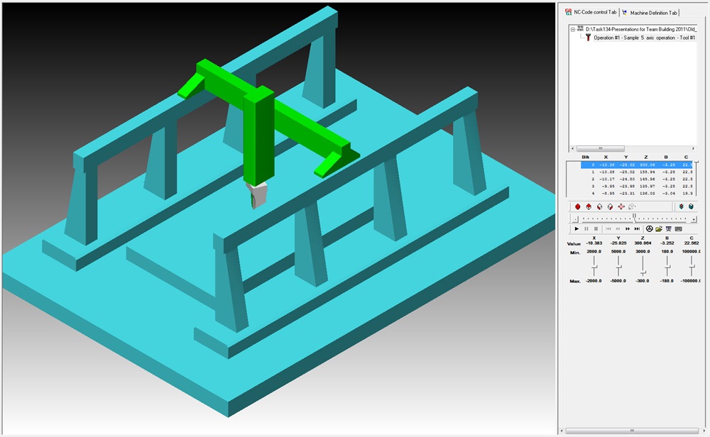
We soon recognised that the most significant risk in five-axis machining was machine
crashes. To address this, we began simulating complete machine kinematics. Given the
complexity of machine geometry, we focused on simplifying it, concentrating on critical
components such as the table, work holding and spindle, while disregarding the housing and
other less critical details.
We discovered that OpenGL, well-developed for gaming, could be leveraged to create fluid
animations of machine movements for any five-axis tool path. The challenge was converting
CAM software tool paths to machine motion. The solution lay in the post processor: its role
is to transform the tool path for the part to machine kinematics, mathematically converting
the tool-axis vector in the workpiece co-ordinate system into rotary axis angle values for the
specific machine.
Since five-axis post processors were rare, we developed this capability in-house. Our post
processor developers provided the kinematic solution, which we connected to an OpenGL
engine. The result was a fast capability for simulating tool paths for any five-axis CNC
machine. By the early 2000s, we showcased this technology at a major exhibition on a large
screen.
While fast, this system initially did not report collisions. Nevertheless, it proved valuable.
We termed it “Visual collision checking”, similar to tool-path back-plotting where users
manually inspect the tool path. Operators could run the simulation, rotate the view with the
mouse and visually determine if collisions would occur. Given the comparative slowness of
computers at that time, this represented a pragmatic solution, offering instant simulation
without waiting time. Users could navigate between the program’s start and end points
simply by moving a slider bar with the mouse, visualising all motions.
We decided that our five-axis tool path should be used in conjunction with this simulation
and bundled them together to prevent machine damage due to inadequate simulation
capabilities. While some customers purchased additional stand-alone simulation packages,
most found our fully integrated simulation extremely helpful since it utilised the same
kinematic solver as the post processor they employed to operate the machine.
As computer hardware became increasingly powerful, our ambitions grew: why not
implement actual collision checking instead of merely visual collision checking? Encouraged
by OpenGL’s success in gaming and how it facilitated our solution development, we
explored further gaming technology and collaborated with an expert who had developed
collision detection engines for the gaming industry. After significant investment and
adaptation to meet industrial needs, we achieved full collision checking, also known as
“clash detection”.
Accustomed to instant simulation capability, we aimed to maintain similar speed levels even
with collision checking. This presented challenges, but we discovered that by reducing the
number of triangles in the triangle mesh model, we could achieve satisfactory speeds.
At this stage, however, we were only addressing machine collisions and gouges of the tool
and spindle against the target workpiece geometry. While we could guarantee that the
target part would not be damaged by the tool and no machine collisions would occur, we
lacked material removal simulation, meaning unexpected cuts into unmachined stock went
undetected, such as a rapid motion crossing the stock. This required material removal
simulation, so we directed users to run the integrated material removal simulation engine
within their CAM software, typically licensed from specialist companies providing such
technology.
In 2005, at an academic conference, I met Dr Stautner from Dortmund University, who had
completed his PhD on material removal simulation technology and subsequently joined our
team. We were receiving numerous customer requests for fully integrated material removal
simulation within the machine simulator.
Upon examining existing market technology, we found that most CAM software utilised a
technology based on mesh Booleans, where tool motion is described as a mesh subtracted
from the stock mesh. While initially quick, the process slowed dramatically as more
Booleans generated increasingly more triangles. We adopted the discrete model originating
from Dortmund University but recognised the substantial work required to ensure accuracy.
Though fast, making the results visually appealing and supporting technologies like turning
and wire cutting presented significant challenges.
By 2015, our journey continued despite our satisfaction with our simulation technology. A
new challenge emerged: how to run the simulation engine on an industrial PC adjacent to
CNC control to prevent machine collisions in real time. This challenge came with the
advantage of receiving information about future machine movements with a one-second
look-ahead, providing data of the “future” one second in advance. Our task was to calculate
collisions and material removal and stop the machine before any issues occurred. This
necessitated significant optimisation of our calculation engine and required heroic efforts
from our team to deliver timely solutions to partners.
We named this technology CAS (Collision Avoidance System) and believe it could eliminate
all machine tool crashes. With the rapid advancement of chip technology, accelerated by
developments in AI, we anticipate that within a few years, even basic chips in CNC controls
will have sufficient performance, eliminating the need for additional industrial PCs.
While CNC machines can avoid collisions using CAS, it requires proper definition of the tool,
holder, work holding and stock geometry for each job. Many CNC machines do not require
such data to cut parts, but it is essential for collision avoidance. Upon investigation, we
determined that all this data exists within CAM software but lacked a standard format for
export to CNC machines – typically, only the NC program was transmitted.
We initiated the development of MDES (Manufacturing Data Exchange Specification) to
enable the export of job set-up data from CAM software to CNC machines running CAS.
Working with approximately 90% of major global CAM vendors and most CNC control
makers and machine tool vendors, we secured substantial support from key industry
players. The adoption of this workflow is progressing. To accelerate adoption, we have
made this specification freely available as an open standard to prevent the proliferation of
competing proprietary standards.
And the story does not end there. NVIDIA’s success with AI means we now benefit from GPU
power. The benchmark results on a mid-range GPU are fascinating: many tool paths with 1-3
million lines of NC code complete simulation at the highest resolution in under 10 seconds. I
confidently assert that material removal simulation should never take more than 10
seconds, regardless of tool-path size. We have achieved this without compromising quality
or taking shortcuts to increase speed. This approach facilitates straightforward retrofitting
for all CAM software companies using our solution, they do not need to change anything for
their users to enjoy this improved performance.
While one team focused on GPU simulation, another team worked with numerous
developers for years on triangulating our discrete model. We discovered that our discrete
model offered many advantages, including linear speed increases with more moves,
numerical stability and memory usage control. However, the triangulation was based on
discretisation.
We found a method to generate perfect triangulation based on customer tolerance
requirements without generating excessive or insufficient triangles while preserving
features like holes, sharp edges and fillets. This significantly improved simulation speed in
“play mode” and substantially accelerated the simulation engine used for updating stock
models between consecutive tool path operations such as roughing and rest-roughing.
As our CAM partners integrate and release these capabilities, users will soon access this
exciting technological suite.
More information www.moduleworks.com