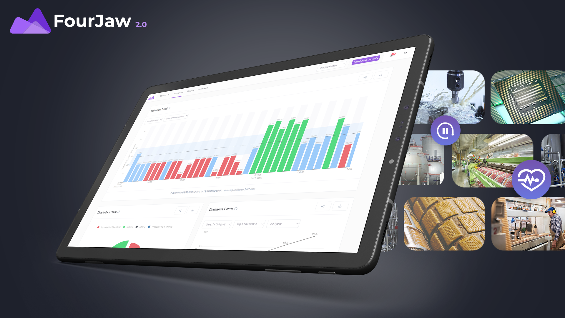
Precision at the push of a button

Changes in ambient temperatures within working environments, as well as machining parts over long periods of time, can impact on a milling machine’s geometry.

GF Machining Solutions’ new Automated Machine Calibration (AMC) helps manufacturers recalibrate their milling machines and recover overall precision at the push of a button.

Over time, any assembled mechanical system becomes prone to losing its original calibration and precision due to heat and external factors: milling machines are no exception. Although Mikron machines are all calibrated at the factory after assembly and during commissioning, changes in a customer’s working environment – including ambient temperature variations and heat generated during the machining process – cause deviations from the original calibration. This effect can often result in process consistency and precision being affected, which in turn impacts on part quality.

To simplify machine calibration, GF Machining Solutions has developed an all-in-one, ready-to-use AMC package which allows operators of both three-and five-axis milling machines to easily and quickly perform a recalibration and recover the overall long-term precision required for high-quality parts.

The AMC cycle consists of both the software for the Heidenhain TNC 640 control, as well as the hardware (a dedicated pallet including a calibration ball and aluminium reference block) for pallet calibration. An easy-to-use ergonomic interface requires little training, while the automatic data management reduces human error, minimises downtime between cycles and increases operator availability.

To recover the machine’s geometry, operators simply start the program and are guided by the interface. AMC assesses and adjusts all key components necessary. Within 10 minutes the machine is recalibrated to its original kinematic precision. GF Machining Solutions currently offers AMC as a standard package on its three- and five-axis Mikron MILL S and Mikron MILL X series.

For further information www.gfms.com

Esprit 4.5 now available

DP Technology, maker of the Esprit CAM system, has released Esprit 4.5, a multifunctional update that includes features such as an enhanced user interface, a new turning feature offset, and new support for circle segment tools.

The updated user interface features clearer, more consistent icons, while the ribbon commands have been reorganised for a more intuitive experience. In addition to improving ease of use, these updates give the Esprit interface a more streamlined, higher-end look and feel.

The new turning feature offset lets the user offset individual elements of a turning feature in the axial and radial directions to program median tolerances or leave stock for subsequent processes, all without modifying geometry. Also included is an offset calculator that allows the user to easily program a target diameter or apply standard ISO tolerances.

Esprit’s new support for circle segment tools lets users parametrically define and create milling tools with oval, barrel, tapered or lens profiles, without the need to create custom tool geometry. These tools offer several benefits over conventional milling tools in many five-axis applications, including larger axial depth of cut, superior surface finish, higher stability and reduced tool wear. As well as simplifying circle segment tool creation, parametric tool definition allows Esprit to better optimise tool-path strategies that use such tools.
“Before we release any product update, we take the time to ensure it’s packed with features that make a difference to our customers,” says Tania Campanelli, director of R&D at DP Technology. “Version 4.5 is dedicated to improving the user experience and, as always, ensuring our customers stay as efficient as possible.”

For further information www.espritcam.com

Global language of production

The VDMA and VDW are joining forces to promote the use and dissemination of OPC UA standards throughout the mechanical engineering sector under the ‘umati’ label.

“Cross-industry and cross-technology marketing will take our customers a significant step forward,” says Dr Wilfried Schäfer, executive director of the VDW (German Machine Tool Builders’ Association). “Manufacturing companies have not only machine tools but their own individual mix of equipment, robots and systems. If all these technologies can exist in a common ecosystem that is ideal for producing plug-and-play solutions, it will save end users a lot of time and money.”
Hartmut Rauen, deputy executive director of the VDMA (German Engineering Federation), adds: “Over 30 specialist groupings in more than 17 associations are working on technology-specific interfaces, known as the ‘Companion Specifications’. This high level of collaboration forms the basis of true, open interoperability between machines and software systems, from the shop floor to the cloud. Only the VDMA has the means to unite the necessary integrative forces from the wide range of production domains.”
The mechanical and plant engineering sector adopted OPC UA as the standard for data exchange from an early stage, largely because OPC UA provides a uniform framework for machine and system interoperability. Having adopted a bottom-up approach, it became clear how important it was to have uniform definitions for basic elements for a large part of the diverse range of products in mechanical and plant engineering. The simplest example is machine identification, including features such as manufacturer, serial number,
year of manufacture and machine type.
Here, various VDMA departments – such as Electrical Drive Engineering, Plastics and Rubber Machinery, Machine Vision, Metallurgy, Robotics and Machine Tools – are currently drawing up the ‘Basic Companion Specification OPC UA for Machinery’. The first version is scheduled for publication later this year.
For further information www.vdw.de

Tool made using VISI helps COVID-19 plan

An injection moulding specialist helped a public school in Rutland to produce thousands of pieces of PPE for frontline workers during the early days of the COVID-19 crisis.

While Oakham School was closed during lockdown, staff used 3D printers and laser cutters from the Design and Technology Department to begin making face shields. The department approached local company, Rutland Plastics, to help it boost productivity, which took the team from manufacturing just a handful, to 8000 a day.
Rutland Plastics’ technical manager Carl Martin says they were originally asked to 3D print a number of headbands for the shields, but decided it would be more cost effective to manufacture a mould tool using its VISI software package, from which the plastic product could be injection moulded.
“We received the initial design for the 3D printed product, and modified it in VISI to make it suitable for injection moulding,” he says. “Once that was completed and approved, we designed the tool in VISI using a Meusburger bolster with aluminium bolster plates.”
The design then went into the tool room and was milled on the company’s Mazak VCN 530C CNC machining centre, with tool paths created through VISI’s CAM functionality. From taking in the initial 3D design, through turning it into a mouldable product, and finalising the mould tool, took less than a week.
When the two-impression mould was set up on Rutland’s 80-tonne Engel moulding machine, both parts of the headband were formed from a medically-accredited polypropylene every 24 seconds during the production run of 25,000. To complete the full screen face masks, Oakham School arranged for the headbands to be attached to plastic visors, which were then distributed to front line NHS staff.
For further information www.visicadcam.com

Major release from ModuleWorks

ModuleWorks has released its 2020.04 CADCAM software components – the first major release of 2020 – which is available now for download from the ModuleWorks website.

Each ModuleWorks release contains new and enhanced features across the product range. This latest release contains new quality-enhancing features for five-axis and three-axis machining, as well as improved visualisation for the MultiXPost post processor.
In five-axis machining it is not always possible to create a collision-free lead for the machining process. The new automatic tilting feature uses an intelligent algorithm to automatically tilt the tool to avoid collisions, thereby improving the safety and efficiency of the machining process, particularly when working with complex tool shapes such as barrel-mill cutters.
Setting the constraints on the lead tilt angle and side tilt angle enables users to adjust the machining process in different ways depending on the tool’s contact point and the machining surface. To provide even more application flexibility, the user-defined contact point and angle limits can now be measured relative to the surface normal, instead of the initial tool orientation. When working with barrel-mill cutters, this feature gives users better control over the cutting conditions upon tool engagement.
With regard to three-axis operations, floor machining for pocket/boss areas is now available to complete the basic product portfolio of roughing and finishing cycles based on a wire-frame geometry. This new cycle creates engrave cuts at a specified depth. The pattern can be used with open and intersecting drive curves and is suitable for engraving text and single-line font machining. To optimise tool loading, users can now create a specified number of engraving tool-path slices with variable depths.
The posting of three-axis tool paths on a machine usually requires constant adjustments to the position of the table or head, which may not always be desired when viewing the simulation. To provide an improved user experience, MultiXPost is now able to eliminate continuous movement and keep the table or head axis in a fixed position while ensuring the whole tool path is simulated within the machine limits.
For further information www.moduleworks.com